IDEA StatiCa Member – Member stability
General introduction
IDEA StatiCa Member is structural engineering software for the structural design and code-check of steel members, including their connections and necessary surroundings beams and columns.

Typical examples of not common steel members
There are many great tools for designing 3D steel frames – SAP2000, Robot Structural Analysis, SCIA Engineer, etc.
They cover almost all requirements of structural steel designers. But still, there are issues with many question marks. Mainly in:
- Connections, details, nodes
- Stability and buckling
IDEA StatiCa is focused on more complex parts of steel structures and offers:
- IDEA StatiCa Connection for checking nodes and connections of any topology
- IDEA StatiCa Member for resolving all unclear topics of stability and buckling
Every structural engineer usually calculates the steel structure in some 3D FEA software. Then, he needs to take steel members one by one and do two main checks for steel members:
- Section check
- Stability check
He uses calculated internal forces and applies analysis formulas mostly defined in the national design code.
The same approach is applied in Member for steel.
Structural engineer calculates steel structure (frame) in 3D FEA software. The analyzed member and all members related to it are separated from the modeled 3D structure and are resolved using CBFEM.
- Global analysis of steel frame is done in 3D FEA software.
- All analyzed members are modeled by CBFEM.
- A simpler model is used for all related members (connected in nodes). Related members can be supported at the end.
- Nodes and connections are designed in IDEA StatiCa Connection UI.
- Specific manufacturing operations can be applied on member – transversal or longitudinal stiffeners, openings, cuts...
- Loads can be applied on members and at the ends of related members (equilibrium principle like in Connection).
- The analyzed member is loaded by standard loads derived from calculated internal forces (during the import of the model and load cases). The user can select the position of the load, e.g. at upper flange of the beam.
- Related members are loaded by standard loads and end internal forces.

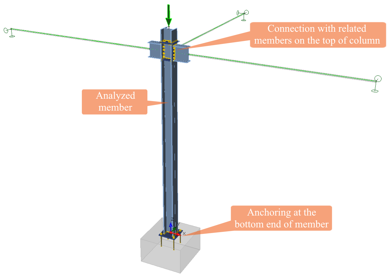
CBFEM model of a column. One analyzed column, four related members, and a precise model of anchoring

CBFEM model of a castellated beam between two columns
The analysis model of Member is created by CBFEM. Member provides three types of analysis:
- MNA – Materially Non-linear Analysis.
- LBA – Linear Buckling Analysis (stability)
- GMNIA – Geometrically and Materially Non-linear Analysis with Imperfections
Structural engineers can do in Member on a much higher level the same check as in standard workflows:
- Section check: MNA is used. A strain check of 5 % is applied.
- Stability check: LBA tells the shape of stability collapse and advises how imperfection should be defined. GMNIA is used afterward. A strain check of 5 % is applied or the attainment of maximum load (end of convergence).
The same model as in IDEA StatiCa Connection – Component Based Finite Element Method – is used:
IDEA StatiCa Connection Theoretical Background
Model description
Application IDEA StatiCa Member works with a multi-level model of the structure with combined loads. The goal is a proper investigation and check of selected members of a structure – “analyzed” members.
Other parts of the model are:
- Related member(s) – all members which are connected to the analyzed member(s)
- Connection(s) – CBFEM connection(s) of analyzed and related members
- End supports on related members
- Loads on analyzed member
- Loads on related members
- End forces on related members

CBFEM model of member as a part of seismic bracing system
The analyzed member is “cut-off” of the structure and investigated separately. All loads on the analyzed member and related members have to be applied as in 3D model of the whole structure. In the places of “cut”, which is done at the ends of related members, the internal forces are applied as actions on members. The cut-off structure loaded in such way is in equilibrium. It means that theoretically, no supports are needed for the analytical model. CBFEM model is more precise than a standard member model. It is a benefit but it also causes the partial infraction of equilibrium. Therefore, it is useful to apply support at the ends of related beams. Supports should be defined to allow the same behavior of cut-off structure as it is in the whole structure. The program lets it on a judgment of a structural engineer.
Analyzed member
The analyzed member is an investigated member upon which loads are directly applied. The loads on the analyzed member can be applied to the member centerline or directly to the individual plates of the member with the real area of loading. Analyzed members are modeled fully with shell elements.
Model of analyzed member
Related members
Related members are divided into stub part adjacent to the analyzed member and simplified part at the rest of the related member. Stub is modeled by shell elements (full CBFEM model) and simplified parts by simple 1D beam elements with six degrees of freedom. Only the necessary part close to the joint with the analyzed member (the stub) is modeled by shell elements to speed up the calculation. The ends of related members are supported by user-defined restriction of translation or rotation in an arbitrary direction in the local coordinates of the related member.
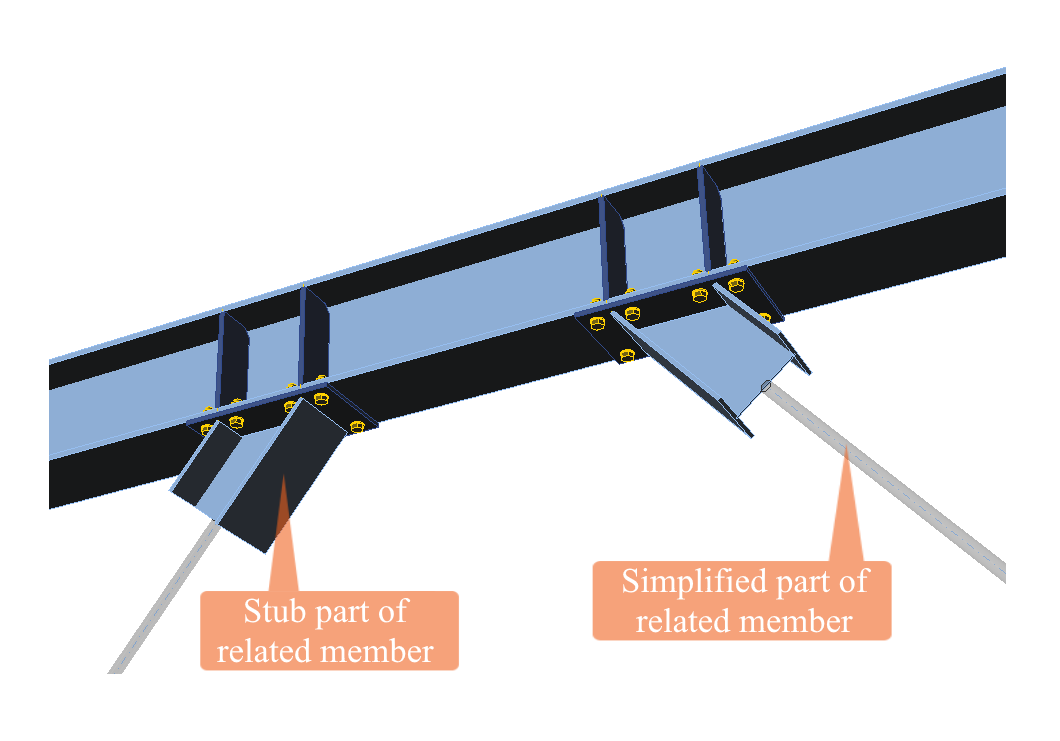
Model of related beams
Connections
Connections between analyzed and related members are properly defined in the way they are modeled in IDEA StatiCa Connection. Note that they are not checked in IDEA StatiCa Member, because this application work with loads critical for the member, not for connections. The proper check of connections shall be done in IDEA StatiCa Connection.
Supports
IDEA StatiCa Member adds the second level of FEA analysis of the selected member(s). The first level is done in the standard 3D FEA program. The second level uses internal forces calculated in the first level. The structure loaded in such way is in equilibrium.
More precise model (e.g. local eccentricities of members, real lengths of members...) and especially imposed imperfections for the GMNIA analysis cause that the equilibrium is not kept. Reasonable support based on structural engineer judgment is recommended.
Standard supports can be defined at the ends of related members. All three translation and three rotations can be eliminated by support. Supports are defined in the local coordinate system of the member.

End supports on related member – purlin; x-direction and all 3 rotations are supported
Loads
The analyzed member (or piece of a structure) must be loaded like it is loaded in the whole structure. Self-weight is not applied automatically; only the user-defined loads are considered. The following loads are applied:
- Line loads on analyzed and related members
- Internal forces in end sections of related members
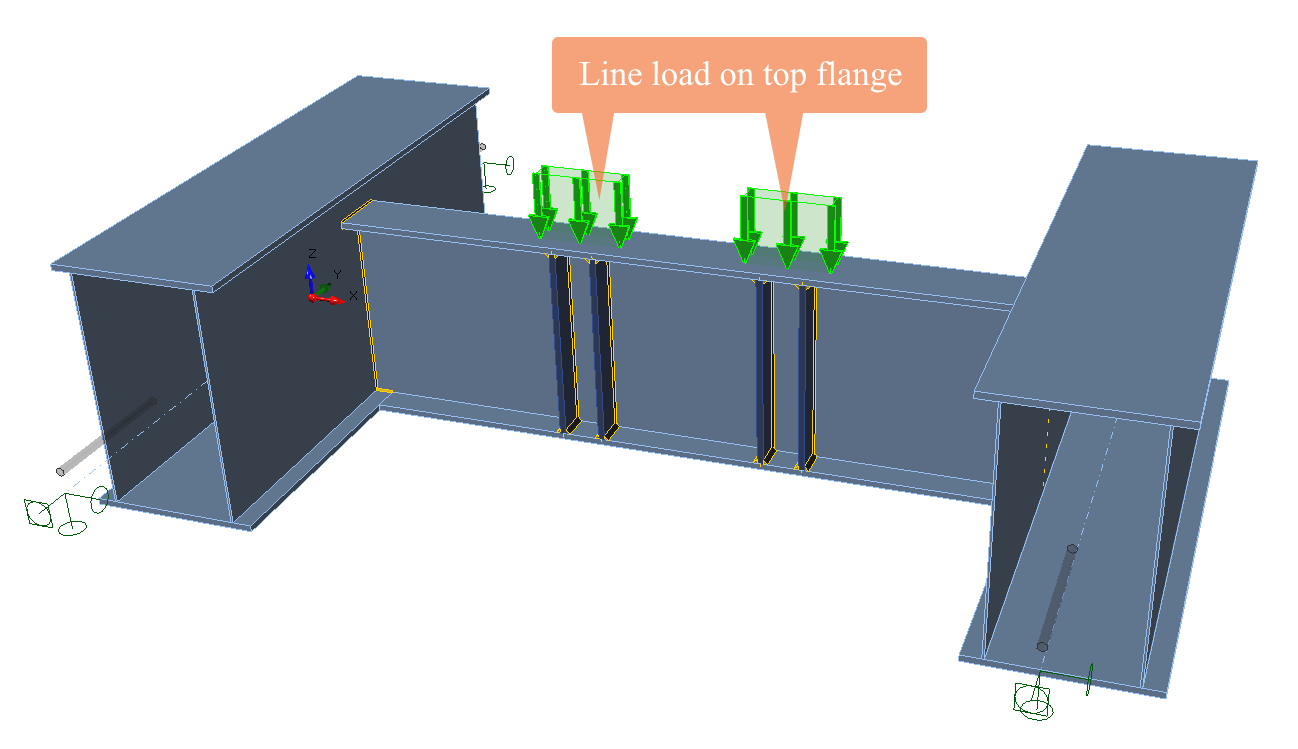
Line loads
The structural engineer knows very well line loads and point loads from 3D FEA software. Such loads are idealized for the purpose of 1D members. They do not exist in real life. The real loads are usually planar, or surface loads, or members are loaded through the connections of other members.
The user can apply line loads on analyzed members, but he must add more details – on which flange or web is the load applied, the width of loaded area, etc. Also, point loads are better to input as planar loads of specific length and width.
Line loads on related members are applied in the standard way as in 3D FEA software.
Point load is input as line load with a specific width
End forces
Internal forces at the end sections of related members. They are applied as actions on related members. It is very similar to loading of members in models of connections in IDEA StatiCa Connection.

Internal forces as load actions at the end of related member
Practical example
The process of CBFEM model assembly is shown on the following example.
Designer needs to check the lateral-torsional buckling resistance of a girder in a frame. If the standard approach is used, the whole frame is calculated in 3D FEA software. Then the girder is checked separately. Boundary conditions are decided; codes usually use assumption of rigid or pinned supports. Generally, even a spring of semi-rigid joint may be selected. The decision is a key factor in the assessment of lateral-torsional buckling resistance and is fully dependent on the designer's estimation. The calculated internal forces are compared to the resistance of lateral-torsional buckling determined by analytical formulas.
Application Member uses completely the same principles. The analyzed member is cut from the full model of the structure. The boundary conditions are not estimated, but all the connecting parts are exactly modeled. The problem of boundary conditions is not completely solved due to the need to support the ends of related members. Supports of related members depend on the designer's decision, but their influence on the load resistance of the analyzed member is smaller by several magnitudes than compared to the standard approach.
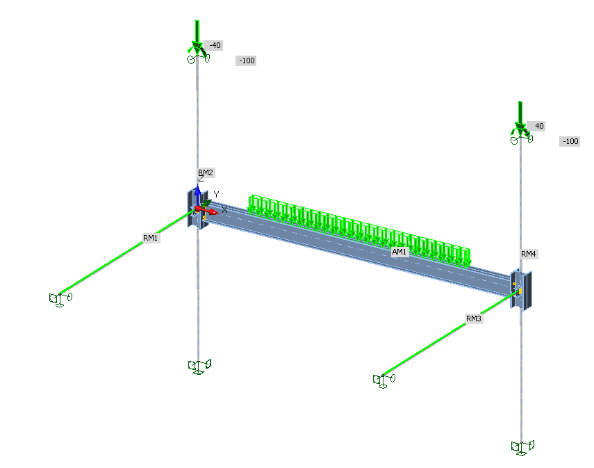
Example of the model of girder with joints, related members, and loads
The analyzed member AM1 – the girder – is loaded by continuous load acting on the upper flange. The joints are modeled and checked in IDEA StatiCa Connection.
Columns are the related members at the model. They are fixed at the bottom. At the top, they are supported only in transverse direction (y, z). That allows loading the columns by the weight of the rest of the structure – by normal force and bending moment in this example. Their magnitudes correspond to the internal forces solved on 3D model in FEA software. There is no other load acting on the columns.
Other related members are the secondary beams. They are simply supported, and the real loads are applied to them along their whole length. At their ends, simple supports are applied with the added restriction of rotation around longitudinal axis x.
Of course, the CBFEM model is also somehow simplified. Nevertheless, it describes the behavior of the analyzed member more precisely than the standard approach based on analytical formulas and estimation of boundary conditions and bending moment diagram.
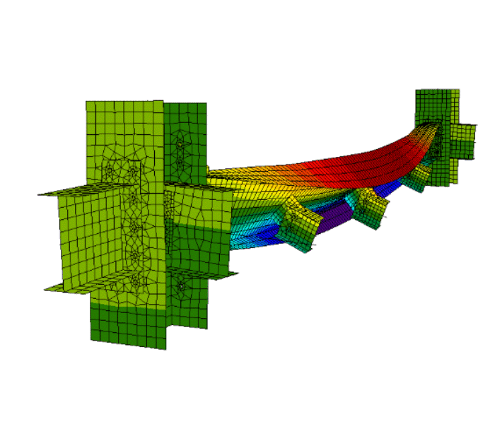
Following figures show the expected behavior of the girder.
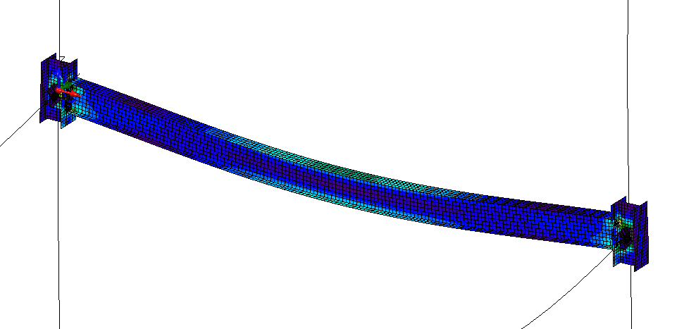
Deformation of the girder determined by MNA

Buckling mode shape determined by LBA
Analysis
IDEA StatiCa Member is able to perform three types of analysis:
- Materially Nonlinear Analysis
- Linear Buckling Analysis
- Geometrically and Materially Nonlinear Analysis with Imperfections
The first two analyzes can be used for code checks of members, e.g. using General method (EN 1993-1-1, Cl. 6.3.4), but mostly they are used for the preparation of the third, most precise, analysis.
Materially Nonlinear Analysis (MNA)
Materially nonlinear and geometrically linear static analysis is sufficient for stocky members without any buckling issues. The aim of application IDEA StatiCa Member is to solve complicated members, so MNA analysis is usually not sufficient for complete assessment. This analysis is required to perform other analysis types.

Material diagrams of steel in numerical models
Linear Buckling Analysis (LBA)
The structure is considered perfect without any geometrical or material imperfections, and the material is elastic in this analysis type. Linear buckling analysis provides factor αcr – minimum amplifier for design loads to reach the elastic critical resistance of the structural component. The factor determines the load when Euler's critical buckling load is reached. The real buckling load of a real, imperfect structure may be much lower, and therefore high safety margin is recommended:
- αcr > 15 – use MNA
- αcr < 15 – use GMNIA
Another result of LBA with the same importance is the buckling mode shape. It provides information which part of the modeled structure loses stability. User should check all the buckling modes and select the important ones for the application of imperfections. The important buckling mode shapes are usually causing sinusoidal half-wave bow deflection of the analyzed member or local buckling of slender plates.

Buckling mode shapes
The buckling mode shape also provides us with information on whether the member fails in flexural buckling around weaker or stronger axis, torsional buckling (axially loaded columns) or lateral-torsional buckling (bent beams) or local buckling (members with slender plates). Note that for complicated structures, buckling mode shapes may combine the buckling of several members with various shapes. Also, if a whole frame is modeled, the frame will buckle as a whole and not columns and the girder separately.

Flexural, torsional, lateral-torsional buckling
To calculate the buckling modes, the Lanczos algorithm is used.
A limitation of this algorithm is that if multiple buckling shapes exist for the same or very similar buckling factor, the method is only able to calculate one of the shapes. This can typically be the case with thin-walled structures, for which the shapes for a single buckling factor can take many forms, so the user should be aware of this limitation.
For every buckling shape, a second buckling shape with the same buckling factor, but the opposite deformation always exists. This should be kept in mind when combining shapes to form an imperfection for GMNIA – the user might want to use a buckling shape with the opposite sign if the resulting shape is more critical in combination with a different buckling mode.
Buckling mode shapes are directly used for the application of imperfections in the most sophisticated analysis type – GMNIA.
Geometrically and Materially Nonlinear Analysis with Imperfections (GMNIA)
Geometrically and materially nonlinear analysis with imperfections is the most sophisticated analysis type for static loading. All the imperfections (varying thickness of plates, out-of-straightness, residual stresses, non-homogeneities in material, misalignment of supports...) are substituted by equivalent geometrical imperfections and can be set using buckling mode shapes calculated by LBA. User selects the maximum amplitude of the buckling mode shape used for imperfection. The description of imperfections is in the next chapter.
Interpretation of results
Most design codes recognize two limit states – serviceability and ultimate.
Serviceability limit state
Design codes provide limits of the deflection of members. These can be checked by comparing the deflection of analyzed member to the limits.
Ultimate limit state
Ultimate limit state may be reached by attainment of a limiting value of the principal membrane strain – recommended as 5 % or attainment of the maximum load for members susceptible to buckling. Maximum load is reached when the solver stops converging (because the model is loaded by forces and not by displacements). End of convergence means that no load increment may be applied to the model, and the analysis may stop below 100 % of defined load. Descending branch of the load-deformation diagram cannot be captured.

End of convergence in GMNIA
Imperfections
The imperfections are inaccuracies in supports, residual stresses in members, variable thicknesses of plates, out-of-straightness of members, etc. All these imperfections are simulated by equivalent geometrical imperfection. Three geometrical imperfection types may be considered:
- Global imperfections of the structure
- Local imperfections of members
- Local imperfections of slender member plates
There are guidelines in e.g. EN 1993-1-1 and EN 1993-1-5 for each imperfection type.
Note that generally, imperfection shapes with positive and negative signs (different directions) should be investigated. Only if the geometry is symmetrical, both imperfection directions provide the same results, and only one may be investigated.
Global imperfections
Global imperfections of the structure are described in EN 1993-1-1, Cl. 5.3.2 (3). The structure should be inclined in the form of equivalent sway imperfection according to the following figure.
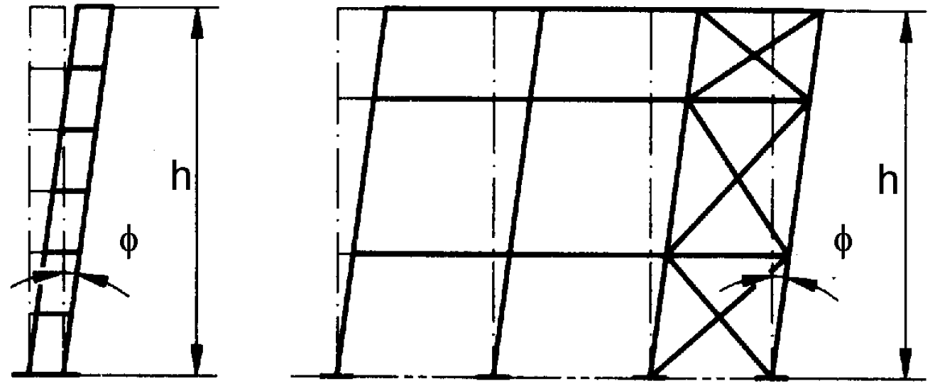
Equivalent sway imperfection (from EN 1993-1-1 – Figure 5.2)
The angle of imperfection is:
\[ \phi = \phi_0 α_h α_m \]
where:
- ϕ0 = 1/200 – basic value of imperfection
- \( 2/3 \le α_h = \frac{2}{\sqrt{h}} \le 1.0 \) – reduction factor for height h applicable to columns
- h – height of the structure in meters
- \( \alpha_m = \sqrt{0.5 \left ( 1+\frac{1}{m} \right )} \) – reduction factor for the number of columns in a row
- m – number of columns in a row, including only those columns which carry a vertical load NEd not less than 50 % of the average value of the column in the vertical plane considered
The global imperfections should be applied to the structure in the global analysis model to obtain correct loads. The global imperfections need not be applied also to the model in application IDEA StatiCa Member if e.g. only one beam is analyzed.
Local imperfections of members
Local imperfections of members are described in EN 1993-1-1, Cl. 5.3.2 (3). The imperfections are considered in the shape of local bow imperfection with the amplitude e0/L, where L is the member theoretical length (node-to-node distance).
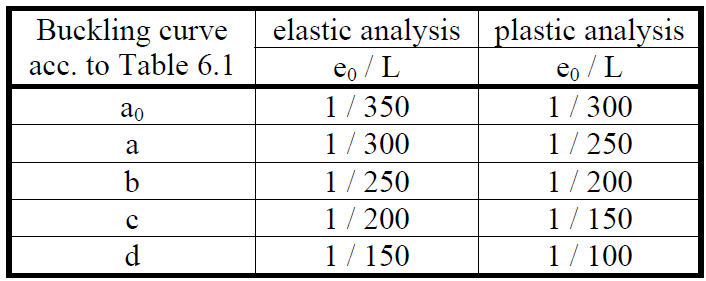
Design values of initial local bow imperfections (from EN 1993-1-1 – Table 5.1)
The plastic analysis is used so the right column of the table should be used. The amplitude e0 should be chosen according to the table above for predominantly compressed members where flexural, torsional or torsional-flexural buckling is expected. If the member is predominantly bended and main failure mode is lateral-torsional buckling, the amplitude e0 may be decreased by factor k = 0.5 according to EN 1993-1-1, Cl. 5.3.4 (3).
Two examples are shown:
Example 1: Column
A column with the length of 4 m is loaded by axial force and has αcr = 1.4 for buckling around a stronger axis and αcr = 1.5 around weaker axis. Other values are significantly higher. Two cases should be checked:
- Buckling around stronger axis: According to Table 6.2, buckling curve, a is selected, which corresponds to amplitude of imperfection e0 / L = 1 / 250 for plastic analysis. Therefore, amplitude 4000 / 250 = 16 mm is applied to the first buckling mode shape. GMNIA is run and the limit states are evaluated.
- Buckling around weaker axis: According to Table 6.2, buckling curve b is selected which corresponds to amplitude of imperfection e0 / L = 1 / 200 for plastic analysis. Therefore, amplitude 4000 / 200 = 20 mm is applied to the second buckling mode shape. GMNIA is run and the limit states are evaluated.
Minimal load resistance should be used. Alternatively, both buckling modes may be used at the same time, which leads to safer result and faster calculation time.
Example 2: Beam
Beam with the theoretical span (node to node distance) of 6 m is loaded by the transverse load. LBA shows that the first buckling mode shape is lateral-torsional buckling with αcr = 1.9. Other buckling mode shapes are with significantly higher values of αcr. According to Table 6.4, buckling curve, a is selected, which corresponds to amplitude e0 / L = 1 / 250. Because lateral-torsional buckling is investigated, factor k0 = 0.5 may be used. Amplitude 0.5 • 6000 / 250 = 12 mm is applied to the first buckling mode. GMNIA is run and the limit states are evaluated
Local imperfections of slender member plates
If members are class 4, local imperfections of plates should also be applied. The panel imperfection amplitude should be a / 200, where a is the shorter panel span according to EN 1993-1-5, Cl. C.5.
Local buckling of slender plates
While GMNIA should be a suitable analysis for the assessment of slender members, currently, not enough verifications and validations were made to confirm that the model is safe. Therefore, it is not recommended to use IDEA StatiCa Member for slender members (class 4) for now.
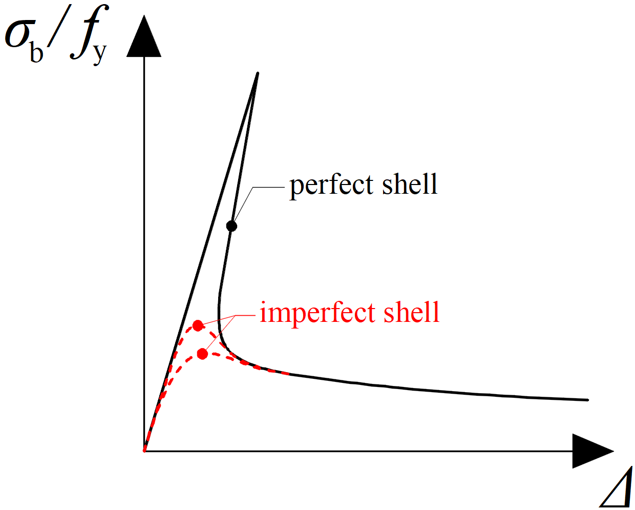
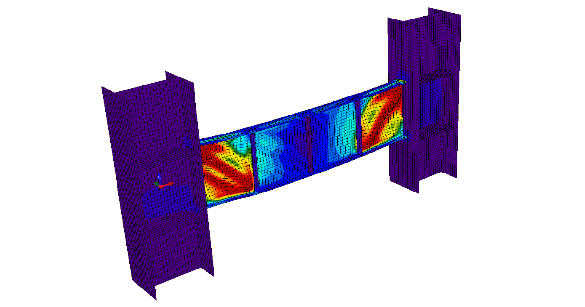
Influence of imperfections on the numerical analysis of slender plates
Applying imperfections in IDEA StatiCa Member
IDEA StatiCa Member allows applying imperfections in the buckling mode shapes with maximal amplitude chosen by user in absolute value. Usually, the first buckling mode shape with the maximum amplitude according to Table 5.1 in EN 1993-1-1 is enough. For members with cross-section class 4, more buckling mode shapes must be considered and a combination of at least two buckling modes used. Especially for a model with more analyzed members, several buckling mode shapes have to be selected.
Geometric imperfections are equivalent and should not enter the evaluation of results, e.g. deflection in serviceability limit state. Therefore, when visualizing the results, only the deflections due to loading are shown on a structure undeformed by imperfections.
Advanced design according to AISC 360-16
AISC 360-16 does not directly refer to the design of members by a finite element analysis using shell elements so it is recommended to use a much more detailed guide in EN 1993-1-5. Comm. 1.3.3b refers to ECCS: Ultimate Limit State Calculation of Sway Frames with Rigid Joints (1984) where the concept of equivalent geometrical imperfection is used. The design by inelastic analysis is covered in Appendix 1.3. The inelastic analysis shall take into account:
- flexural, shear, axial and torsional member deformations, and all other component and connection deformations that contribute to the displacements of the structure – covered by use of GMNIA and member consisting of shell elements
- second-order effects (including P-Δ, P-δ, and twisting effects) – covered by use of GMNIA
- geometric imperfections – set by the user by using buckling mode shape from LBA analysis
- stiffness reductions due to inelasticity, including partial yielding of the cross-section that may be accentuated by the presence of residual stresses – it is not possible to set residual stress in the member. However, using Appendix 1.3.3c, residual stress modeling may be replaced by reduction of the elastic modulus, E, and modulus in shear, G, by 0.8.
- uncertainty in system, member, and connection strength and stiffness – covered by use of geometrical imperfections and stiffness reduction
Appendix 1.3.3b states: "In all cases, the analysis shall directly model the effects of initial imperfections due to both points of intersection of members displaced from their nominal locations (system imperfections), and initial out-of-straightness or offsets of members along their length (member imperfections). The magnitude of the initial displacements shall be the maximum amount considered in the design; the pattern of initial displacements shall be such that it provides the greatest destabilizing effect."
Geometric imperfections are described in Comm. C2.2: "Initial geometric imperfections are conservatively assumed equal to the maximum material, fabrication and erection tolerances permitted in the AISC Code of Standard Practice (AISC, 2016a): a member out-of-straightness equal to L / 1000, where L is the member length between brace or framing points, and a frame out-of-plumbness equal to H / 500, where H is the story height."
It is recommended to apply out-of-plumbness in the 3D FEA software and out-of-straightness in IDEA StatiCa Member application.
Summary:
If it is decided to use the AISC approach, apply out-of-plumbness H / 500 in 3D FEA software, out-of-straightness L / 1000 in Member and reduce the modulus of elasticity in tension/compression and shear by factor 0.8. Note that this procedure does not cover complicated issues with several buckling mode factors close to each other.